| ??? 02/09/08 20:27 Read: times |
#150530 - photo Responding to: ???'s previous message |

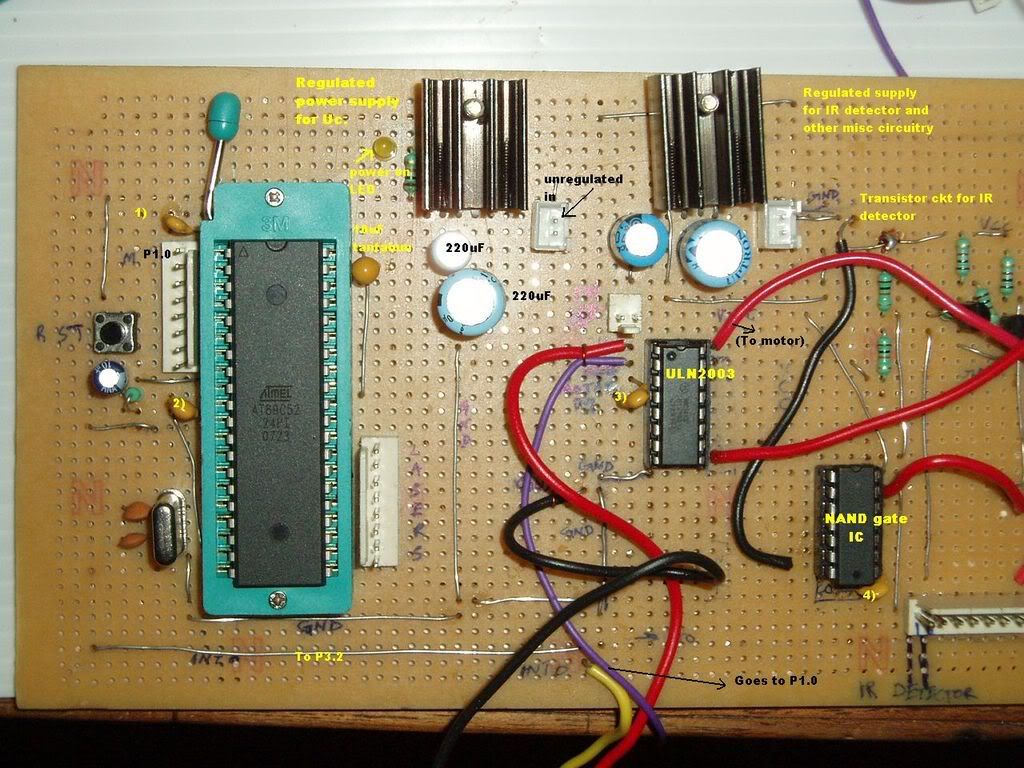
I am an absolute noob at this, so i cannot say that the board looks very pretty...infact, it looks like a crows nest even to me :) 1,2,3 &4 are 100nF ceramic caps.. ive added a 10 uF tantalum as close as i could (added after my first post-thanks to the suggestions i received here...certainly a HUGE improvement) ( which is much more than 2.54mm as suggested- impossible for me to do that!)) I'll start from the beginning-- part of my task involves controlling and maintaining the speed of a brushless dc motor using a feedback system. This consists of a simple IR led & detector setup and a small vane like obstruction on the spinning motor blocking and unblocking the IR light to the detector. the detector output is given to P3.2 ( int0). My program worked, and the motor did spin slower than full throttle. i hooked up the cro to P3.2 to calculate the rpm and...noise! P1.0 showed an extremely noisy pwm output. I realized that i had a bad problem when the microcontroller int0 (P3.2)used to trigger at the falling edge( which it is supposed to) and at the rising edge( not supposed to happen!)( wrote a small test prog for this) the weird nand( i did not have any other logic gate ic around) setup was actually stuff i added as an afterthought thinking that the noise and double triggering was due to the bare transistor input to P3.2( int0)the reasoning was that a logic gate must output either a 1 or a 0, nothing in between... i'm using a separate regulator for the micro controller. the external hardware has another regulator with a separate power supply.the grounds are connected to each other. the uln2003 driver ic is connected to the motor, which again has a separate 12v power supply. adding the tant and ceramics has greatly diminished the noise( now lesser than 75 mV- cro probe at vcc pin of microcontroller as well as p3.2 and p1.0) but i still have double triggering of int0. |


